This site has been archived and is no longer updated
For current information please refer to the following pages
- VISTA is operated by ESO
- ESO Homepage
- Information about observing
- ESO - VIRCAM @ VISTA
- Information about surveys
- ESO - Public Surveys Projects
 |
- |
| Survey processing |
- |
External Links |
near IR surveys |
| 2MASS |
UKIDSS (in north) |
Visible and
Infrared |
|||||||||||||||||||||||||||||||||||||||||||||||||||||||||||||||||||||||||||||||||||||||||||||||||||||||||||||||||||||||||||||||||||||||
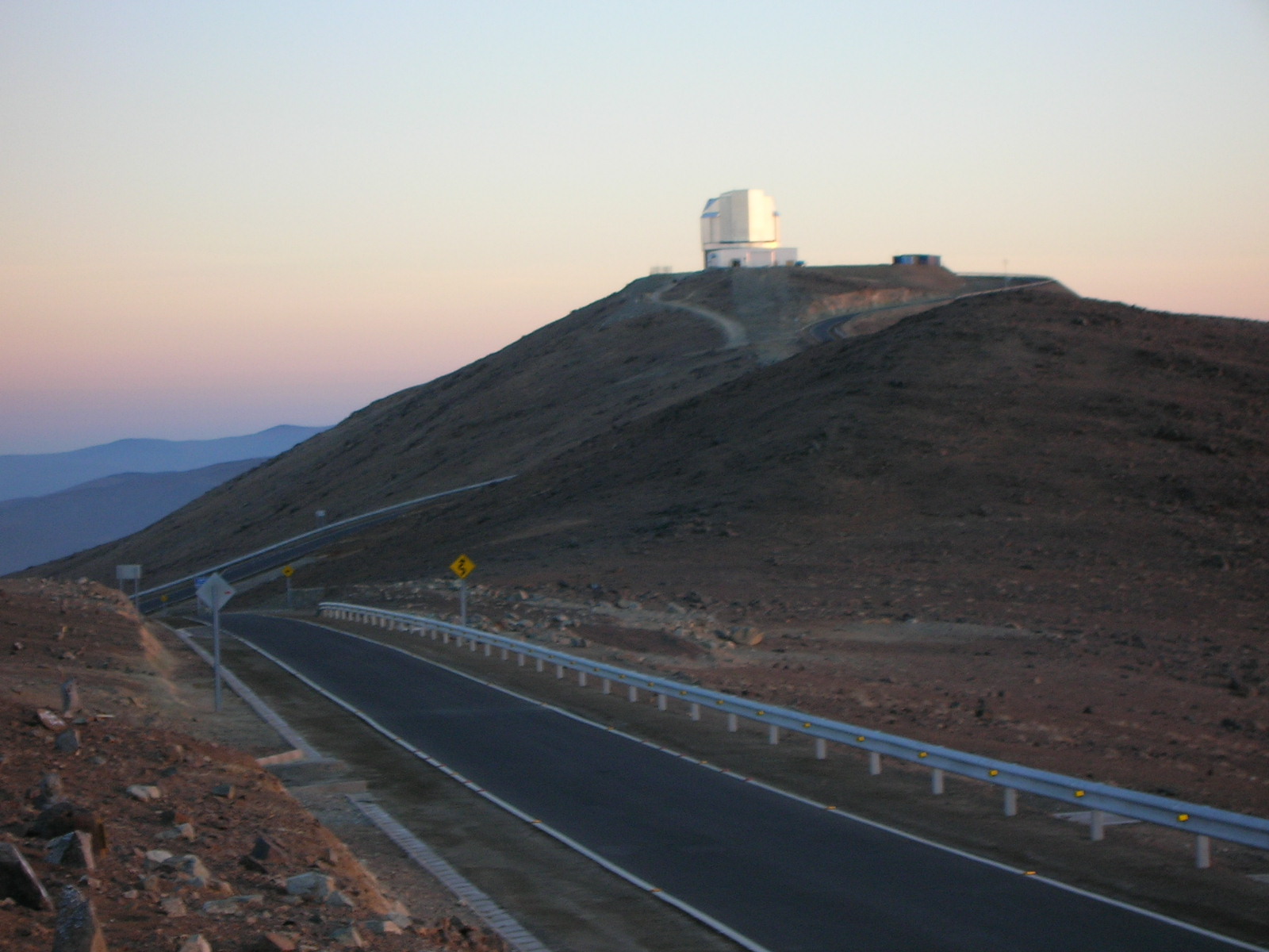
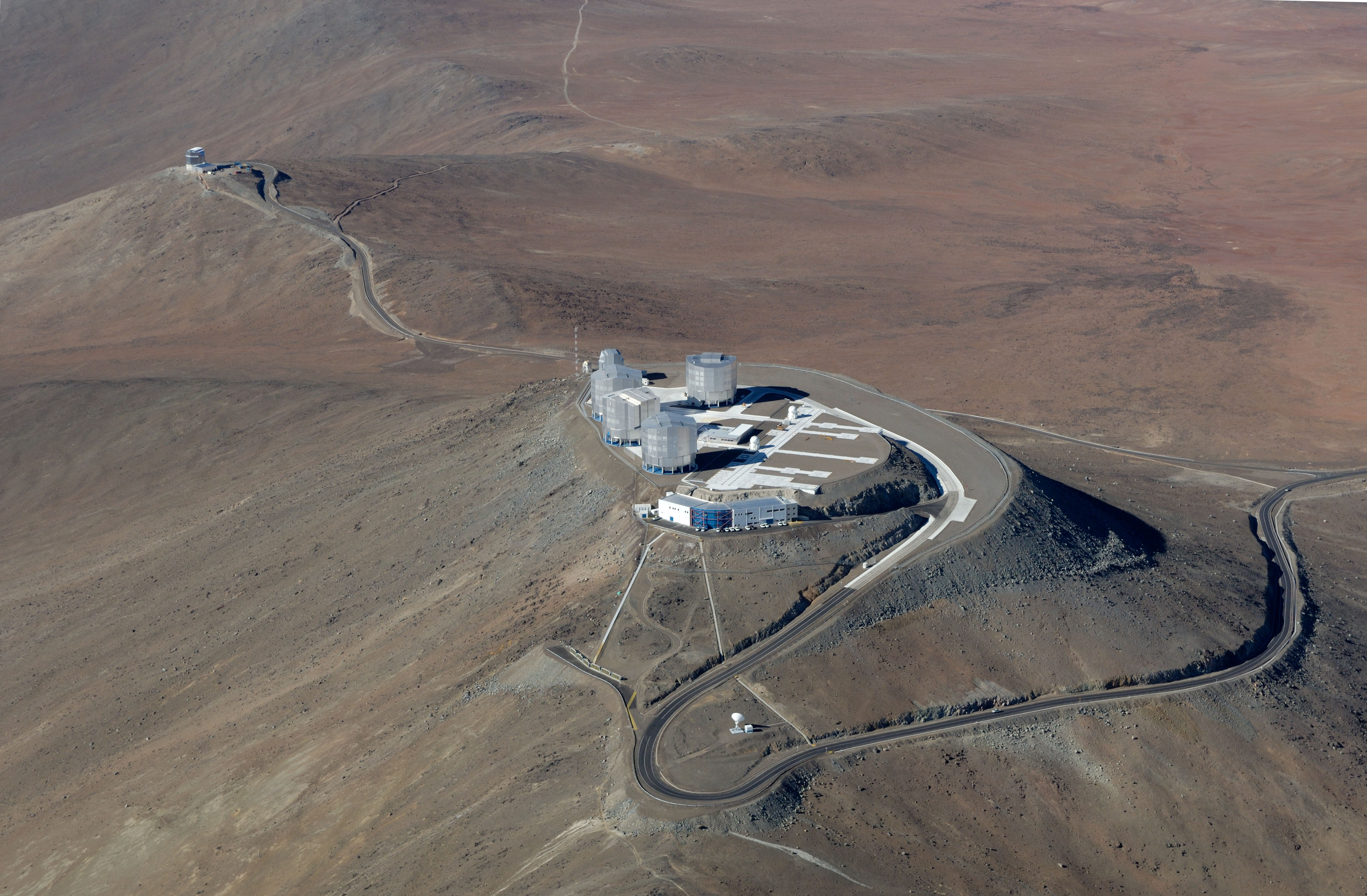
NewsOverviewVISTA is a 4-m class wide field survey telescope for the southern hemisphere, equipped with a near infrared camera (1.65 degree diameter field of view at VISTA's nominal pixel size) containing 67 million pixels of mean size 0.34 arcsec and available broad band filters at Z,Y,J,H,Ks and a narrow band filter at 1.18 micron. A wide field visible camera, if constructed, could also be used on VISTA. The telescope has an azimuth-altitude mount, and quasi-Ritchey-Chretien optics with a fast f/1 primary mirror giving an f/3.25 focus to the instrument at Cassegrain. The instrument mounts to the rotator on the back of the primary mirror cell, and includes a wide-field corrector lens system (3 infrasil lenses), autoguider and active optics sensors. VISTA is located at ESO's Cerro Paranal Observatory in Chile (latitude 24° 40' S - see Google satellite picture ) on its own peak (see picture) about 1500m from the four VLTs and the VST see either (figure where VISTA is at top left) or (figure where VISTA is at bottom right). The point spread function (PSF) of the telescope+camera system (including pixels) is designed to have a full width at half maximum (FWHM) of 0.51 arcsec. Seeing, and other weather realted statistics for Cerro Paranal are given at ESO's Astroclimatology of Paranal pages and the VISTA site is expected to have similar conditions. The site, telescope aperture, wide field, and high quantum efficiency detectors will make VISTA the world's outstanding ground based near-IR survey instrument. Time available75% of the VISTA time available to ESO will be available for large scale public surveys and the remaining 25% for smaller proprietary surveys. On the assumption that VISTA is unavailable ~10 nights a year for maintenance the corresponding numbers of nights per year are Public Surveys: ~236 nights, Proprietary Surveys: ~78 Nights. In planning surveys it should be realised that the surveys as a whole (public + proprietary) have to effectively use the range of seeing and sky conditions (sky brightness, extinction, wind speed) available, as well as the RA range. One of the roles of the Public Survey Panel for VISTA will be to ensure that the final Public surveys form a realistic set in the light of these constraints. Information on the conditions at the Cerro Paranal Observatory can be found on the ESO Astroclimatology of Paranal pages. For all observing time at ESO telescopes ESO assume These numbers are used at submission time as approximate indications of time available (but not, for example, when later scheduling allocated service-mode observations). Filters
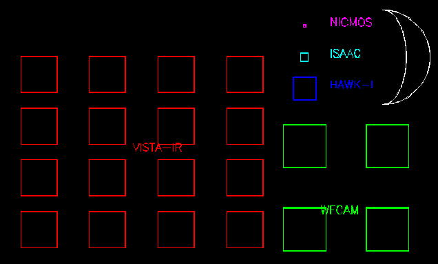
The only moving part in the camera is the filter wheel. With the current complement of Z, Y, J, H, Ks and NB1.18 filters there is one filter wheel position available to hold a further set of 16 filters (1 per detector). Purchase of other filters are under discussion by various groups - see VISTA twiki filters page Field DistortionThe plate scale varies with distance from the field centre, getting larger from centre to edge, which is why the mean pixel size (of 0.339 arcsec) is quoted. The rectangular focal plane, when projected onto the sky, suffers barrel distortion. This means that a somewhat larger area of sky is seen by the detectors than if there was no distortion. A rectangular area of sky when imaged onto the focal plane suffers from pincushion distortion. This means that a somewhat smaller area of focal plane is covered by the sky than if there was no distortion. The distortions (of order 30 pixels at the edge) therefore increase overlap between adjacent tiles and do need not be considered in observation planning. Covering an area of skyThe sixteen 2048x2048 pixel IR detectors (Raytheon VIRGO HgCdTe 0.84-2.5 micron) in the camera are not buttable and are arranged as in the following figure 
which shows a diagram of the focal plane as would be seen looking directly down the camera body (down the Z-axis which on the telescope points towards the sky). On the sky (in the default instrument rotator position) +Y corresponds to N, and +X to East. Below - photograph of the real focal plane. 
A single Integration of length DIT secs (or a coadded series of these known as an Exposure) produces a sparsely sampled image of the sky known as a Pawprint (in red in the following Figure). The area of sky covered by the pixels of a pawprint is 0.6 sq degrees. For comparison the fields of view of NICMOS, ISAAC, HAWK-I and WFCAM are shown below in Figure 2 together with a crescent moon.
and an mockup up of a pawprint showing the Moon 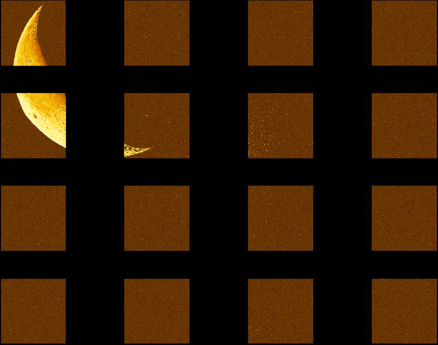
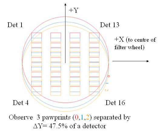
To 'fill-in' the gaps between the detectors to produce a single filled Tile with reasonably uniform sky coverage the minimum number of pointed observations (with fixed offsets) required is 6 which is achieved first by observing at 3 positions offset in Y i.e.
so that after 3 positions in Y an area of vertical side 5.275 detector widths (=4+3*0.425) is covered at least twice. This corresponds to 1.017 degrees (61 arcmin) at VISTA's mean pixel size. There is also a strip at the top and another at the bottom which is only covered once by this tiling pattern. These strips are each 0.475 of a detector height. Each corresponding to 0.092 degrees (5.5 arcmin) at VISTA's mean pixel size. Then a position shift is made in X as shown below 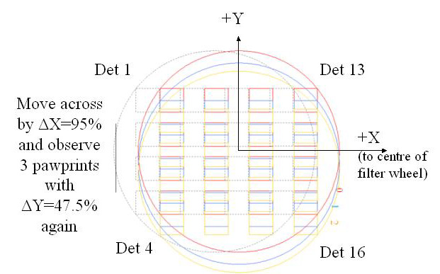
so that the 2 positions in X cover a horizontal side 7.65 detector widths (=4+3*0.90+0.95) with no strips at the +/-X edges. This corresponds to 1.475 degrees (88.5 arcmin) at VISTA's nominal pixel size. The 3 steps in Y are then repeated at the nex position in X. So after 3x2=6 steps an area of 5.275x7.65=40.354 detector areas corresponding to 1.017 deg x 1.475deg = 1.501 deg2 sky is (almost) uniformly covered (by a minimum of 2 pixels) as shown in light green in the exposure time map below for a filled tile (no jitter).
where dark green = 1, light green = 2, magenta = 3, red = 4, yellow = 6, in units of the single-pawprint exposure time. The dark green areas at top and bottom of the plot are each 1.475 deg x 0.092 deg =0.135 sq deg and can be overlapped by corresponding areas from adjacent tiles for many surveys. Assigning only one of the two 0.092 deg overlap (top & bottom) to each of the two tiles involved in an overlap, the result is that each tile, when part of a filled larger area, would covers (1.017+0.092) x1.475 = 1.636 deg2 which will be covered at least twice.
Jitter and microstepsTo deal with bad pixels and to determine the sky level a Jitter pattern of exposures at positions each shifted by a small movement (<30 arcsec) from the reference position will generally be used. Unlike a microstep the non-integral part of the shifts is any fractional number of pixels. Each position of a jitter pattern can contain a microstep pattern. To better sample the PSF a Microstep pattern about a reference position can be performed with shifts specified as a odd number of 0.5 of a pixel (i.e. no integer pixel shifts), which allows the pixels in the series to be interleaved in an effort to improve the sampling. Due to distortion, microsteps should be not larger than 3 arcsec to keep the shifts close to a half-integer number of pixels across the entire field. The calibration software will not handle larger microsteps. Guide stars, wave-front sensor stars, survey area definitionEach integration requires a guide star for the autoguider to use, and one star each for the two low order wavefront sensors which are used to adjust the secondary mirror unit to keep focus and image quality in the fast (f/1) primary beam. For a given sky area specified with respect to a sky position a Survey Area Definition Tool (SADT) will lay down the appropriate grid of pawprints required, and automatically find the guide and wave front sensor stars to produce (in conjunction with P2PP) the Observation Blocks (OBs). This tool is not needed to define a VISTA science program and will be available in Phase II in time for use by successful proposers. Estimating On Source Observing TimeFor estimating required exposure times the Exposure Time Calculator (ETC) is given an object of a given magnitude for which it can determine either a) the signal to noise achieved in a given exposure time or b) the exposure time needed to achieve a given signal to noise see Exposure Time Calculator description page for more detail and the link to the actual ETC. Estimating OverheadsAs with any telescope there are overheads associated with observing. VISTA is intended to survey quickly, primarily through having a large field of view, but the actual survey speeds obtained (in good conditions) will depend on the way in which observations are carried out. 1) Overheads making a single tile in one filterOverheads on a tile depend on the adopted combination, and order, of filter changes, microstepping, jittering, and tiling. As an example a typical minute spent on the sky in a fixed filter such as Ks might consist of (6 x [DIT=10 sec] integrations + 1 sec readout), coadd + save, 3 sec jitter move, 1 sec guider lock), repeat => 70 sec elapsed time for 60 sec on sky. The 'Observing Strategy' section in 'Observing Setup' section of the Exposure Time Calculator allows you to break a total on-source time down into a number Ndit of individual Integrations, each DIT seconds long, with the Ndit*DIT long Exposures repeated Nexp times with a number of jitters, Njitter, and if required a NxM microstep pattern. The ETC then returns the total on sky time and the elapsed time so that the overheads are known and the observing strategy can be adjusted to maximise the survey efficiency see Exposure Time Calculator description page for more detail. However the user will also need to seperately account, by hand, for the overheads 2), 3) and 4) below which are not calculated by the ETC or other available tools):2) Filter change overheads (not in ETC)The filter change time depends on the wheel rotation from the last position but is between 25sec (to move between neighbouring filters) and 60 sec (to move between the most distant filters). Filter changes may be done in parallel with a position change. 3) Tile change overheads (not in ETC)There are three components to the time taken to go from one tile to another. i) Slewing/presetting in Az and Alt each of which is addressed in turn below i) The time to go to a new tile will depend on how far away it is in altitude and azimuth from the current position, and on the zenith distance. As for any alt-azimuth telescope at VISTA’s latitude one wants to minimise presets between objects with Dec < -24° to Dec > -24° and vice versa. Both alt and azimuth can accelerate at 0.5°/s^2 and max angular velocity is 2°/s, so it takes a 4-sec ramp-up to reach max angular velocity (and covers 4 deg in those 4 sec). The Cassegrain rotator is faster (1°/s^2 and 3.6°/s) so will hardly ever be the limiting overhead. The “worst case” preset is a 270° azimuth move from SE to NE which has to go the long way round via W due to the cable wrap, and which will take ~140 seconds. These situations should be avoided, if at all possible, during scheduling. ii) Checking and acquiring the new guide star will impose a short overhead of ~1 second. iii) After a telescope slew giving a large (> 10°?) change in altitude there may be a need for a ~30-sec pause for one closed-loop low-order wavefront sensing (LOWFS) cycle to complete and update the M2 position before science observing re-starts. All these numbers will be updated when there is sufficient experience with the on-sky behaviour of the real system. 4) Active Optics overheads (not in ETC)A Low Order Wavefront Sensor (LOWFS) is used to update the position of the secondary mirror during observations, and needs data for a minimum time of ~30sec to smooth out seeing variations. The LOWFS can operate in parallel with science observations. If the telescope is staying in one position for >/= ~30sec there is no associated overhead as the LOWFS exposures merely start just after and finish just before the science integrations finish. However using the LOWFS in this basic mode implies a minimum time between jitter moves of ~30sec. If it is essential to jitter more often than every 30 sec, this can be done using open-loop M2 control, though a slight loss of image quality may result. With experience on sky we will learn that after tracking the same sky area for X minutes one needs to do an LOWFS update. The value of (probably X~15) will become clear during commissioning. In case that image quality falls off more quickly, or that one wants to observe for longer than X minutes before presetting to a new part of the sky, the telescope would by have to stay where it was with the camera idle until the LOWFS has accumulated enough (~ 30sec) exposure time. As an alternative the AO control system could be changed to internally coadd LOWFS frames to give the necessary exposure from shorter exposures with the star moving on the chip between exposures. This mode remains to be implemented and will then need to be tested on sky.
VISTA Data Processing and Archiving----------------------- There is a VISTA Public Surveys discussion forum Twiki ----------------------- ESO pages on Public Surveys including VISTAESO Survey Team Presentation on ESO Public Surveys - Dec 2007 |

| Page updated 2019
May 04 by J.P.Emerson to whom comments should be sent [ESO][VISTA Home] |